FROM G.W. Rodriguez
Standby Sound 126
We’ve all experienced those cues we build that are very demanding of our Stage Managers. We want a cue to happen at the exact moment of an action. In my most recent case, I was the Sound Designer for THE RESISTIBLE RISE OF ARTURO UI by Bertolt Brecht.
Scene ten is a trial where many witnesses are questioned. In between each witness the Judge uses their gavel, the lights go to black in a zero count, and a loud gavel sound happens. There’s also a similar effect to start the next witness.
For the timing to work, it was critical that the Stage Manager call sound and lights at the exact moment the actor hit the gavel base. To solve this problem, I decided to build a force sensor that would trigger the lighting and sound cues.
The documentation of such devices are quite rare. The following is the details of my design for the trigger, what parts were used, and what code was used. This isn’t meant to be the best, most effective, or even cheapest solution. Just one detailed example.
Ingredients
-
1 – Force Sensitive Resistor https://www.sparkfun.com/products/9376
-
2 – Arduino Uno https://store.arduino.cc/usa/arduino-uno-rev3
-
2 – XBee Wifi Module https://www.sparkfun.com/products/12568
-
1 – 1MΩ Resistor
-
2 – Project boxes
-
2 – Breadboards with patch cables
-
1 – Gigabit switch
-
1 – MacPro
-
1 – ETC Ion
Software
-
QLab 4 (with pro audio license)
-
Max 7
-
Digi XCTU Software
The Design
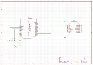
The Force Sensitive Resistor (FSR), essentially increases its resistance when force is applied. It can detected 100g to 100Kg, but it can handle a larger amount of force (even though it can’t detect it).
When I hooked up the FSR (Fig. 1), reading the values (between 0-1024) on the Arduino by printing A0 to serial was simple (Fig. 2). This took me all of fifteen minutes to put together. When I experimented with putting the sensor under the gavel based I realized the base was spreading out the force too much. So I put some felt under the FSR so the base would transfer more force when being struck by the sensor.
![]() Wireless
Wireless
This part was quite challenging. Programming the XBee’s is difficult because there’s no documentation, so I had to rely on attempting to interpret terrible YouTube videos — which where mostly for series one modules and I was using a series two.
Essentially the FSR is read by the Arduino, which writes to the XBee, and is received by the second XBee. These wireless modules connect to a Wireless Access Point, and although you can have them acquire their IP Addresses via DHCP, I found it too unpredictable because you have to program which other XBee you want to transmit to. So I used static IP Addresses for both modules.
Triggering
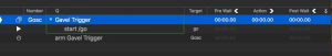
Here’s the signal flow: Sensor -> Arduino -> XBee (Transmit) ~ XBee (Receive) -> Arduino -> Max -> QLab -> Eos (Ion). It is in the Max patch that I do all the logic of deciding how much force I want to be the threshold (see Figure 3), and that sends out an OSC message to QLab (see Figure 4).
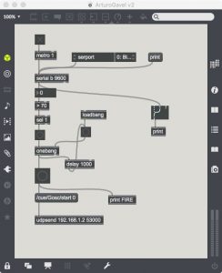 You’ll notice that in Max I’m sending an OSC message not just to hit “Go”, but to trigger a specific cue number “Gosc”. This allowed me to have the Stage Manager call a cue to enable the trigger, which enabled the group numbered “Gosc”. Once it received a successful trigger, it would self disable.
It’s also worth pointing out that I had this cue call “Go” on the main cue list. That way if there was a malfunction of some kind, the operator could manually fire the cue. I also put the OSC command to trigger the lights within the main cue list cues, that way if the sensor triggered it, or the board operator did, it would fire the next light cue.
For examples of the sensor in action, please check out the following videos:
Prototype:
In Action